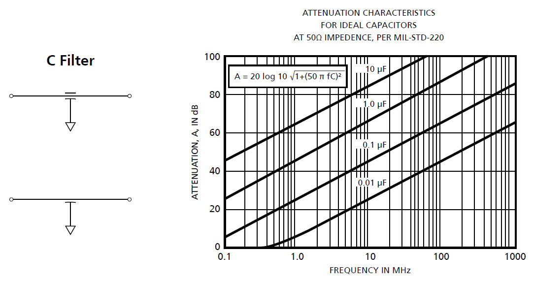
Feedthrough Capacitor — A single element, a capacitor from line to ground, with a through wire connecting the input to output. It has attenuation characteristics that increase at 20dB per decade from its cutoff frequency to at least that frequency where it exhibits a minimum attenuation of 60dB. It maintains this attenuation at higher frequencies.A feedthrough capacitor filter is usually the best choice for filtering lines that exhibit very high impedance. Its schematic symbol and its attenuation characteristics are shown below. A feedthrough capacitor is called a C filter.
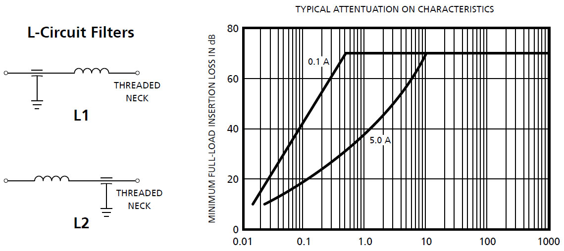
L Circuit — Two elements: a feedthrough capacitor from line to ground, and an inductor connected in series with it between the input and output terminals. The capacitive element can be placed on either the line or load side of the filter, making it either a capacitive or inductive input. Its attenuation increases at 40dB per decade from its cutoff frequency to at least that frequency where it exhibits a minimum attenuation of 70 dB. It maintains this level at higher frequencies.
L-Circuit filters are usually the best choices when the line and load impedances exhibit large differences in impedance. The inductive element is best placed so that it faces the lower impedance.
Schematic symbols and typical attenuation characteristics are shown below. They are commonly referred to as L filters.
L1 indicates that the inductive element is on the end with the threaded mounting neck.
L2 indicates that the capacitive element is on the end with the threaded mounting neck.
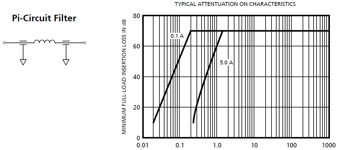
Pi Circuit — A three section filter consisting of two feedthrough capacitors to ground with a series inductor between them. The Pi filter is usually symmetrical, but circumstances sometimes warrent use of asymmetrical Pi circuits.
A Pi filter has attenuation characteristics that increase at 60dB per decade from its cutoff frequency to at least that frequency where it exhibits a minimum attenuation of 80 dB. It maintains this level at higher frequencies.
A Pi filter is usually the best choice when high levels of attenuation are required and where input and output impedances are similar values. It should not be used with switching circuits.
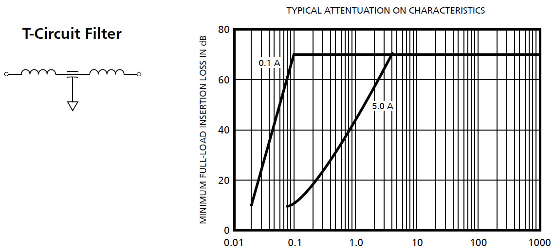
T Circuit — A three-section filter consisting of two series-connected inductors between the input and output terminals, with a feedthrough capacitor between them from line to ground. The T filter is usually symmetrical (identical inductive elements), but circumstances sometimes warrent use of asymmetrical circuits.
A T filter has attenuation characteristics that increase at 60 dB from its cutoff frequency to at least that frequency where it exhibits a minimum attenuation of 70dB. It maintains this level at higher frequencies. A T circuit filter is usually the best choice where both input and output impedances are low. The schematic symbol and typical attenuation characteristics are shown below.
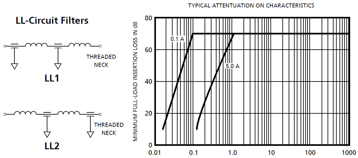
LL Circuit — Four section filter consisting of two feedthrough capacitors connected between line and ground with two interspersed inductors connected in series with them between the input and output terminals.
The LL filter is usually made with identical capacitor and inductor elements.
LL1 filters have an inductive element closest to the end with the threaded mounting neck.
LL2 filters have a capacitive element adjacent to the end with the threaded mounting neck. An LL has attenuation characteristics that increase at 80 dB per decade from its cutoff frequency to that frequency where its attenuation is at least 90 dB. It maintains this level at higher frequencies.
LL circuit filters are used where extremely high attenuation is required and where input and output impedances vary significantly.
